Design and Construction of Long Light Path (LLP) Flowcell
 Madeline Davis is a current chemistry undergraduate at the University of Hawaii at Manoa and will graduate with a B.S. in chemistry 2022. She is currently working at the Measures lab in the oceanography department working on method development of trace nutrient determinations. She is also a scientific diver and a DFA pro instructor for the University’s Dive Safety Operations. https://davisoceanlabcom.wordpress.com
Design and Construction of Long Light Path (LLP) Flowcell
This novel-type of a flowcell is not described in general literature and therefore, it is useful to offer details of its construction. A linear light path (LLP) flow cell facilitates high sensitivity of absorbance measurements, using spectrophotometric methods. LLP can be up to 100 cm long, depending on the desired sensitivity.
Flowcell Set Up
Parts Diagram (Figure 1 shows):
- A. Blue Ferrule (x5)
- B. O-Rings (x5)
- C. Male Connectors (x5)
- D. Acrylic Connector With 3 Ports
- E. Acrylic Connector With 2 Ports
- F. 0.8 mm Green PEEK Tubing (X cm)
- G. External Supporting Tube
Construction
To achieve transmission of light within the flowcell, green PEEK tubing of 0.8mm must be kept straight by using an external supporting tube. It is also important to cut both ends of piece of green PEEK tubing at a 45-degree angle. This is to ensure a good optical contact with the optical fiber and the flowcell, while allowing a free flow of liquid through. If the flowcell tubing is not cut at a 45-degree angle, the optical fibers will be flat against each other, which blocks flow.
Order of fittings is very specific to ensure no leakage occurs. For all fittings, regardless of tubing type, should go in this order: fiber/tubing, male connector (C), blue ferrule (A), O-ring (B).
The External supporting tube will have the green PEEK tubing inserted through it and is best to assemble before attaching to the acrylic connectors.
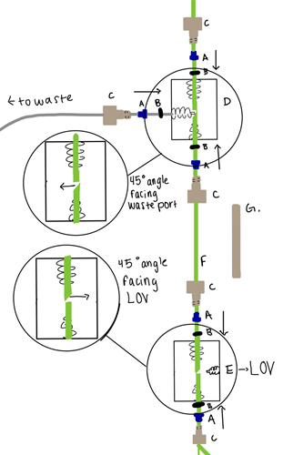 Figure 1: Long Light Path (LLP) Flowcell blueprint
It is recommended to place a 40 psi flow restrictor at the waste line (Figure 2), past the flowcell to prevent formation of air bubbles within the flow system.
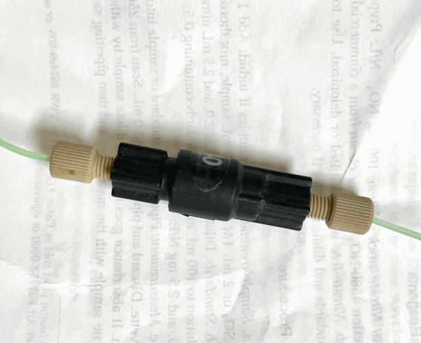 Figure 2: Flow Restrictor 40 psi
Optical Fibers:
Optical fibers were made as shown in Figure 4, where PEEK tubing (A), Quartz Optical Fibers (B), and two component epoxy glue (C). Optical fiber used was silica optical fiber 600 core, 660 clad, 710 buffer by Polymicrotechnologies, and was encased within the PEEK:
- Cut 100 cm of green PEEK tubing (A) and 120 cm of optical fiber.
- Insert fiber (B) into the tubing
- Mix two component epoxy glue and apply as shown (C).
- Move fiber several times 2 to 3 cm back and forth to bring the glue inside the tubing as shown.
- Wipe ALL glue from the outside of the tube and fiber. Let cure.
- Cut the extending fiber square and polish the end. On the other end of the fiber, attach SNS connector.
![Figure 3: 20 cm Flowcell [2] GC_1-4.png](/getattachment/Flowtutorial/Guest-Contributions/Madeline-Davis/GC_1-4.png.aspx?width=265&height=500) Figure 3: 20 cm Flowcell [2]
Figure 3: 20 cm Flowcell [2]
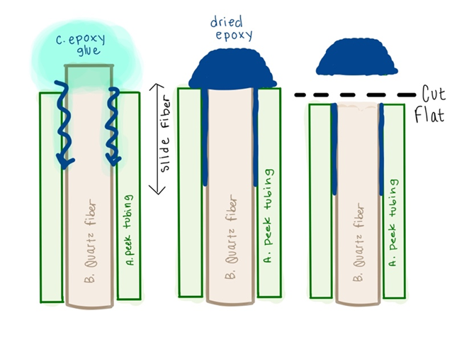 Figure 4: Optical Fiber Construction
Construction of Cadmium Column
Cadmium columns are widely used for the reduction of NO3- to NO2-. While they have been described many times in current literature, we offer a description of this design as it is compatible with LOV manifold.
The column is 3.5 cm long has internal diameter of 3 mm and is filled with 20-60 mesh size Cd granules (GFS Chemicals CAS #7440-43-9). Add the Cd to the column using a small funnel to avoid getting particles stuck within the threads at the end of the column.
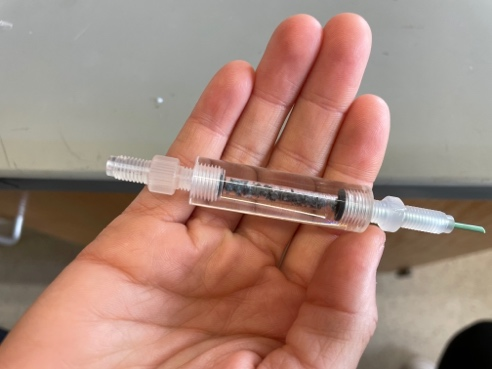 Figure 5: Cadmium Column Example
Parts Diagram:
- A. Threaded Column
- B. Threaded Male Connectors (x2)
- C. Threaded Female Connector T
- D. Threaded T Male Connector (x3)
- E. Holding Coil #3
- F. Blue Ferrule (x6)
- G. O-ring (x4)
- H. Bypass
Construction:
When assembling the column, as shown in Figure 6, it is best to start at the part that goes into port 6. After assembling those fittings use a funnel to add the Cd granules into part A, then resume by connecting parts C and D. Attach the column to the LOV first by inserting it into port 6, then attach the bypass at port 5. It is important to avoid twisting the bypass tubing. Also, pay close attention to the length of the bypass, its internal volume is an important parameter used in optimizing the system, and it should not strain the fitting connection at port 6.
The ends of the green PEEK tubing must be cut at a 45-degree angle and should be placed so that they sit at the base of the column thread. It is also crucial that O-rings form a complete seal, to avoid leakage of particles.
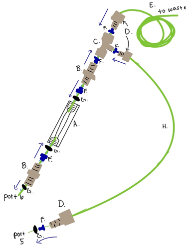 Figure 6: Cadmium Column Construction
Conditioning:
Once packed and attached to the LOV, the order of treatment of the Cd granules is critical to its successful use.
First wash the granules with DI water at a flow rate of 300 µL/sec for 5 minutes, this is to remove all the air bubbles and eliminate any small Cd particles from the column.
Next, use a 1M HCl solution to thoroughly clean the granules they should turn from being a dull grey color to shiny during this process. Once “shininess” is achieved, the column should be rinsed with DI.
Next, prepare a 3% w/w CuSO4 solution, and run this solution through the column. Only 30 seconds of exposure is needed on the column, or until all particles turn black, this results in the column now being activated.
Once the column is activated it must only ever have buffered solutions passed through it, not DI.
An activated column needs to be “shocked” with a concentrated NO3- solution before it will achieve the reduction capacity needed for the methodology to work, this is achieved as follows:
Prepare a 50 µM NO3 solution and let it sit on the column for a few minutes. Then flush the column with buffer carrier at a high flow rate for a few minutes. Rinse the column with 0.6M HCl, and then rinse again with buffer. It is advisable to repeat this “shocking” process about 2-3x, before attempting a test run. Sometimes the column activation will need more “shocking” depending on the length and size of column, as well as the type of granules used.
Further details of determination of NO3- are given in Hatta et. al 2021.
References
[1] Hatta, Mariko, et al. “Programmable Flow Injection in Batch Mode: Determination of Nutrients in Sea Water by Using a Single, Salinity Independent Calibration Line, Obtained with Standards Prepared in Distilled Water.” Talanta, vol. 232, 2021, p. 122354., https://doi.org/10.1016/j.talanta.2021.122354.
[2] Hatta, Mariko, et al. “The Performance of a New Linear Light Path Flow Cell Is Compared with a Liquid Core Waveguide and the Linear Cell Is Used for Spectrophotometric Determination of Nitrite in Sea Water at Nanomolar Concentrations.” Talanta, vol. 219, 2020, p. 121240., https://doi.org/10.1016/j.talanta.2020.121240.