2.1.2. Multi-line manifolds and confluence mixing
The key feature of multiline FI manifolds (A) systems is the confluence point (B), where two streams merge at a T formed junction. Stream merging promotes an instant radial mixing resulting in an even concentration of reagent along the entire length of the injected sample zone.
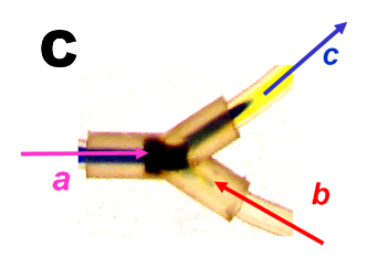
 Rapid and complete mixing at confluence is promoted by local turbulence, as shown in the photograph (C) and visualized by the movie clips, All images were obtained by merging a blue stream of pH indicator (a - blue in basic form) with a colorless stream of acid (b). Because this acid base reaction is very fast, the rate of formation of the yellow color (c) depicts the rate of mixing.

In the first clip (A) a sample zone of an indicator (bromothymol blue) in 0.01M borax solution (pH=9.2) is pumped throughout the spiral coil, passing the confluence point, at which no reagent stream is being added.
In the second clip (B) the same experiment is repeated, however, at the confluence point 0.1M acetic acid (pH=3.3) is added, at an equal flow rate. The indicator (pk =7.4) changes the color from blue to yellow and, since neutralization reaction is extremely fast, it becomes clear that merging streams blend in an instant within confluence point and its immediate vicinity.
Therefore, the conduit downstream from confluence point generally termed as “mixing coil” does not enhance further mixing of sample with reagent. Its function is to furnish incubation time that will promote formation of reaction product. Therefore, length and volume of this flowthrough reactor as well as and applied flowrate should be designed accordingly.
For stop flow reaction rate measurement, the conduit between confluence point and flow cell should be as short as possible. This is because formation and monitoring of reaction product takes place within the flow cell, where reaction mixture is held by stopping the flow.
For flow through monitoring of reaction products, the reactor should be designed large enough to accommodate rection mixture for incubation time long enough to yield an optimized concentration of reaction products. Thus, for incubation time of 20 seconds at flow rate 3 mL/min (50 µL/sec) and channel diameter 0.8 mm (volume 5µL/cm) the reactor coil should be 2 m long. By slowing the flow rate the length of reactor can be reduced accordingly, but then another limitation comes into play. At e.g. flow rate of 0,6ml/min (10 µL/sec) reactor length would be 40 cm. However, the problem is that pump should maintain flowrate within 3% of set value – 300 nL/sec an unrealistic goal for peristaltic pump (Fig. 2.1.7.1.B) In summary selecting length of reactor coil at continuous flow mode is a compromise between incubation time, reaction rates, and sample throughput, an optimizing process of trial and error. Flow programming that uses stop flow reaction rate method facilitates a systematic approach to optimization.