2.1.8. Components and Instruments
Flow injection instrument can be acquired in two ways: By self-construction or by purchasing setup from a commercial source. A majority of research work is done on instruments assembled from commercially available components, because self-made instruments are versatile and can be tailored to specific goals of a project.
Commercially available instruments are designed to serve a dedicated task, such as serial assay of a large number of samples for e.g. nutrients in soil extracts or water. It is therefore important to investigate instrument specifications to ensure that the system is versatile enough to be compatible with intended purpose.
2.1.8.1. Components
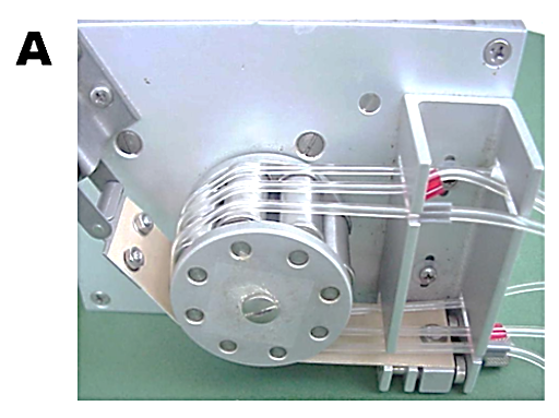
Peristaltic pumps (A) are still the most frequently used drives
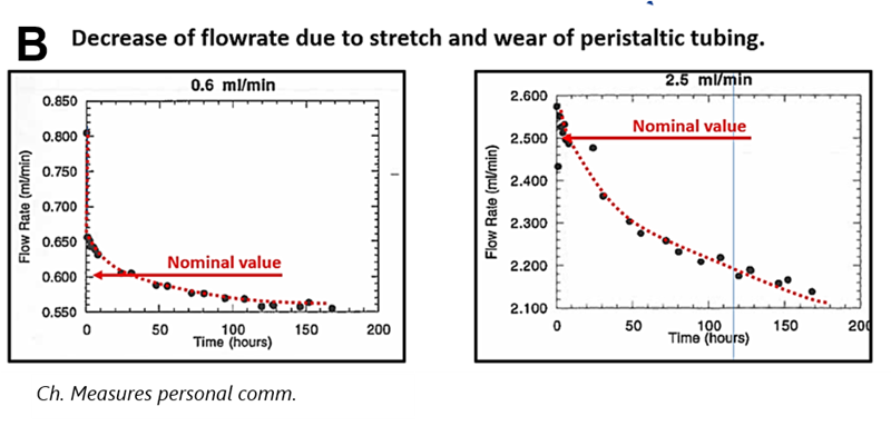
for FI systems, because they generate continuous flow in several parallel channels, where flow rates can be easily adjusted by rotation rate of a drum and by I.D. of the peristaltic tubing. Contributing to the popularity of peristaltic pumps is their apparent low cost, although the price of consumables – the peristaltic tubing- exceeds many times the purchase price of the pump over its lifetime. The largest drawback of peristaltic pumping is the elasticity of the tubing, causing flow rate to decrease during use (B). Therefore, the instrument has to be frequently calibrated and peristaltic tubing has to be replaced.
 A two position, six port injection valve (C) with a fixed loop is the most frequently used for injection of well-defined sample volumes. The volume of the external is selected between 20 and 100 µL by changing the length and I.D. of the tubing. The valve can be switched from load to inject mode manually or automatically, and the loop can be filled either manually by syringe, or automatically from an autosampler by means of a pump. It is important to keep the length of the conduit between sample container and port #4 as short as possible, to save sample material, and to avoid sample-to-sample cross contamination.

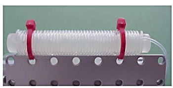
Reaction coils and interconnections are made with Polypropylene, Teflon or PEEK tubing I.D. 0.8 mm. There are many tubing materials available for construction of reactor coils and connection lines. Teflon and PEEK are the most frequently used polymers. Most polymer tubing is translucent and is often color coded, so that tubing I.D. can be identified at glance.
 Ferrules are designed to grip tubing while the connector and nut are being tightened. Since all FIA systems operate at low pressure, it is not necessary to use connectors designed for HPLC. It is, however, very important to use nuts, ferrules, and fittings from a single manufacturer, preferably IDEX as products from different sources are incompatible, resulting in leaks.

Design of opthical flow cells falls into two categories: free standing flow cells and fiber optic flow cells. Fiber optics revolutionized design of Flow Injection instruments by facilitating the placement of a flow cell into best position on a flow path. While in earlier generations of FI instruments the flow channel had to be long enough to reach inside into a bulky photometer, equipped with a flow through cuvette, the present designs use optic fibers to connect a flow cell situated on an optimized position on a flow path, with a light source and a spectrophotometer.This freedom of configuration also led to development of long optical path flow cells for UV-VIS spectrophotometry and chemiluminiscence.
Thus, for UV-VIS spectrophotometry, while in the past the 1 cm long light path flow through cuvette was the only choice, there is now a variety of fiber optic flowcells available.
Long light path flow cell in the range between 5 cm and 50 cm can be self made from readily available components. (see also M. Davis in Guest Contributions)
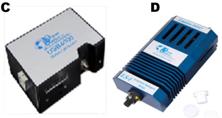
Spectrophotometer (C) and light source (D) are, most frequently used detection systems. The USB4000 spectrometers are optic UV-VIS-NIR detection systems for low light level applications. These spectrometers accept light energy through single-strand optical fibers, and disperse it on a fixed grating across the CCD array. Available spectral ranges are: for colorimetry 200-850 nm, and 350-1000 nm, and for fluorescence 350-1000 nm.
2.1.8.2. Instruments
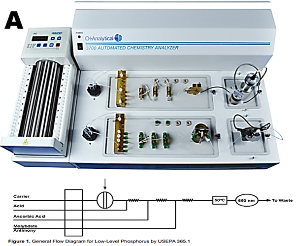
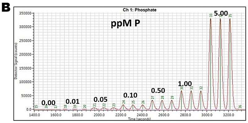
Commercially available instruments vary considerably in design and applicability. The design falls into two categories: “black box” and “open architecture”. The purpose of black box design is to minimize users input on the instrument configuration, including the software programming. While the design makes these instruments ideally suited for routine serial assays, the trouble shooting and maintenance has to be carried out by professional service making the user captive of a given brand. Lachat Quickchem 8500 instrument designed some 40yrs a a vast portfolio of anes, determined in a variety of materials similar two channel architecture albeit in updated technology has OI Analytical FS 3700 Analyzer (A) shown here in two channel version. Configured for phosphate assay it covers range of 0 to 5 ppm P at a sampling rate 45 s/hr with lowest quantifiable concentration of 10 ppb P. (B).
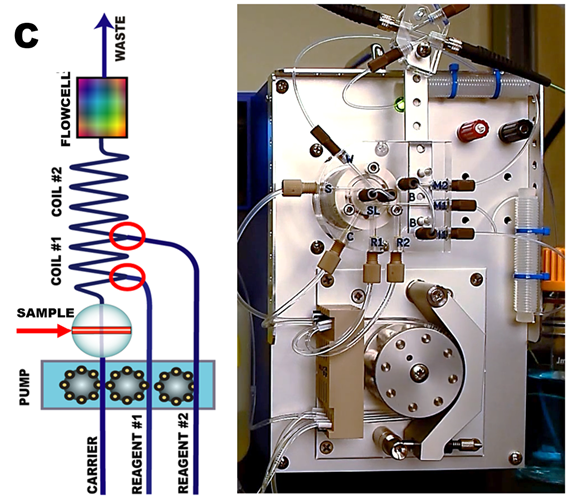
FIAlab 1000 analyzer (C) designed for serial assays that can be performed at sampling rate up to 120s/hr has an open architecture that allows restructuring of flow path. This versatility makes the instrument suitable for research as well as to be used as “front end” Atomic Absorption, ICP or as platform for separation by Sorbent Extraction or Gas Diffusion. All components of flow path, pump tubes, injection valved, coiled reactors and fiber optic flow cell are visible and accessible on a vertically ascending flow path.
