Flow Injection fluidics
It follows from the foregoing that design of flow path from injector to detector should promote radial and minimize axial dispersion. This is achieved by disrupting the laminar flow:
- by distorting the flow path
- by merging steams
- by reversing the flow
The flow is distorted by coiling (A), knitting, or by constraining (B) a conduit.
Merging of streams (C) at confluence point is the essential component of majority of flow injection designs.
Flow reversal (D) is the most efficient approach for enhancement of radial dispersion, and it is the key component of flow programming.

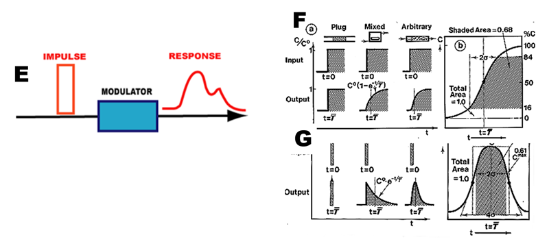
To optimize performance of FI system, however, not only radial dispersion should be maximized, and axial dispersion should be minimized but also the length of residence time of sample, during its travel between injector and detector should be sufficient to allow chemical reactions to proceed. Optimizing function of any reaction vessel is facilitated by using the impulse-response technique, which is treated in depth in textbooks on chemical reaction engineering. (Levenspiel 1972)
The impulse-response technique (E) is based on addition of tracer, either as step (F), or pulse (G), at the inlet of a vessel, which can be monitored at the exit. The resulting residence time distribution curve (RTD) is described by its statistical moments and evaluates flow system as a “black box” regardless of flow conditions within. Therefore, IR technique is suitable for optimization of continuous as well as of programmable flow injection.
 For plug flow the input and output are identical. For mixed flow, the step input (F) is transformed to exponentially growing F-curve. For a pulse input (G) into an exponentially decreasing C-curve.
The arbitrary flow, to which Flow Injection systems conform, the slope of the F curve (F) and symmetry the C curve (G) will increase with the number of mixing stages through which the sample plug has passed. The standard deviation of these curves equals axial dispersion and the time span between the input and the mean of the output curve is mean residence time. The F-curve is an integral of C-curve.
O. Levenspiel “Chemical Reactor Engineering.” 2nd Ed. Wiley NY. 1972