From laminar to turbulent flow
Continuous flow through an open, straight circular tube maintains a laminar flow pattern, until linear flow velocity increases to a value when “birth of eddies” is observed, and turbulent conditions prevail (Reynolds 1883). The breakdown of laminar flow takes place when Reynolds number Re >= 2000. Therefore, Flow Injection system is assumed to function at laminar flow conditions because it operates at Re= 260 since a typical FI channel has 0.8 mm I.D. with carrier stream moving at flow rate 4 mL/min.
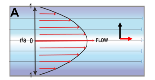
Under laminar flow conditions all fluid elements follow streamlines parallel to the direction of flow (A). At this, Poiseuille flow, the velocity profile has a parabolic shape because velocity u at the tube walls is zero, it reaches maximum value, which equals double of mean velocity at the center of the tube where r = 0. The flow velocity u at any coordinate is:
 where r is the radial distance and a is the radius of channel, while ū is mean flow velocity.

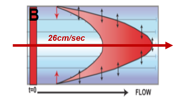
Therefore, a sample zone, of initially square profile, injected at t = 0, will disperse along the velocity profile, forming a hollow, bullet shaped, three-dimensional concentration gradient (B). While traveling through a detector the gradient will yield a sharp, asymmetric peak with long tailing section caused by the slow movement of streamlines adjacent to the walls. In typical Flow Injection conditions, the central streamline will travel at velocity of 26 cm/sec, thus dispersing, within 10 seconds the sample zone through entire 2.5m long flow path between injector and flow through cell. Obviously, axial dispersion must be minimized by breaking the laminar flow, as otherwise FIA concept can not be implemented.

O. Reynolds, Proceedings of Royal Society of London, 35, 84-99 (1883)