3.2.1. Concept and Instrument
Integration of confluence point into lab-on-valve manifold may appear to be a small adjustment of lab-on-valve architecture, but it leads to redesign of the way in which sample and reagents are presently metered, mixed, and monitored (Ruzicka 2018).
In conventional FI protocol, the injected sample moves downstream, on the way to detector through series of confluence points and mixing coils, the number of which corresponds to number of reagents used. Consequently different reagent based assays must be accommodated in different manifolds.
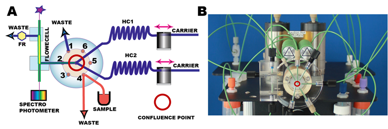
 In pFI flow protocol sample zone moves upstream into holding coil (HC1) (A, B). Next, flow reversal caries sample through confluence point, where reagent is added, into second holding coil (HC2). The final flow reversal brings reaction mixture into the detector. This single reagent protocol is extended to multi reagent protocols by moving sample zone back and forth through confluence point while adding required reagents. Consequently, a wide variety of reagent based assays can be accommodated in the same LOV manifold – as it will be shown in the following sections.
The second novel feature of pFI method is that it can be programmed to perform measurement in two modes:
- Flow (nonequilibrium) and
- Batch (equilibrium)
The flow mode yields the same response (a peak) as the conventional FI, because monitoring takes place while the sample zone moves through flow cell. In this mode, the incubation time, that allows reactions to proceed, is obtained by trapping Sample in Holding Coil. The SHC mode, similarly to cFI yields response based on combination physical dispersion and ensuing chemical reactions neither of them reaching equilibrium.
The Stop in Flow Cell mode yields response that depicts the reaction rate of chemical reactions taking place while reacting sample is trapped in flow cell. SFC can be also programmed in Batch mode, a feature that leads to better reproducibility and higher sensitivity of flow based determinations (Ch.3.2.4.).

The key features of pFI-LOV instrument are:
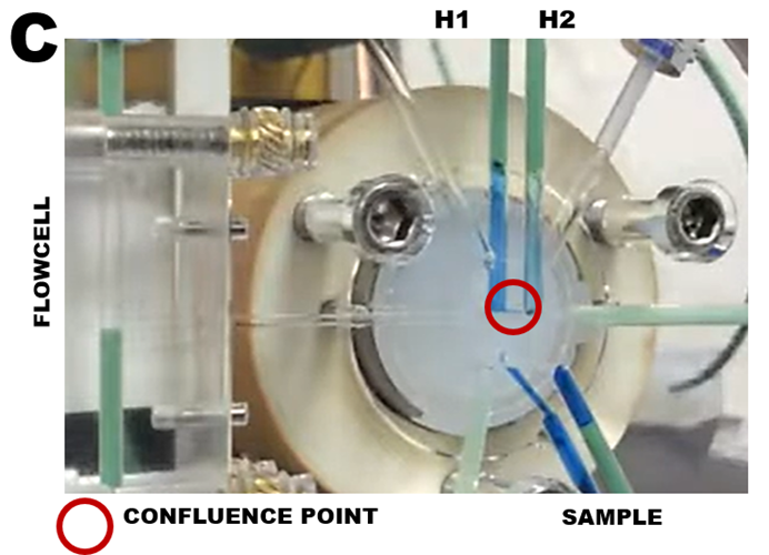
The flow path, that has uniform inner diameter (0.8mm I.D., volume 5 µL/cm) and includes holding coils, lab-on-valve (C), and long light path flow cell. The volume between confluence point and flow cell inlet is 40 µL, while 20 cm long flow cell has volume of 100 µL.
Use of deionized water (DI) as carrier, rising the flow path before and after each measurement.
Setting zero absorbance for spectrophotometry at the outset of each measurement cycle, when flow cell is filled with DI water. This provides the same, reproducible reference zero for all assay protocols, a feature that facilitates correlation of results obtained at different times, on different instruments and at different locations.
J. Ruzicka “Redesigning flow injection after 40 years of development: Flow Programming” Talanta 176 (2018) 437–443.