2.1.1. Principle and single line system
Flow Injection Analysis (FIA) was invented in 1974 (D 1) and documented in series of publications when it was applied to analysis of real life samples in cooperation of Danish and Brazilian scientists (D 2 to D 18) while its theoretical foundation was laid down (D 20). By 2021 almost 23.000 papers were published on FIA and related techniques as listed in Hansen’s Database. The Database can be searched by topic, author, or by reference number.
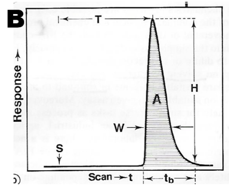
The simplest, single stream, flow injection system (A) uses a pump that propels a carrier stream through an injection valve and into a reactor coil, and through a detector. By using continuous and constant flow rate, it is assured that series of standards and samples are treated in exactly the same manner as they flow from injector to detector. This allows calibrations to be applied to assays of unknown samples, even if the equilibria of chemical reactions are not reached. Calibration is based on measurement of the height H of a peak at a time T recorded on an analog response (B).

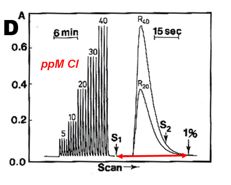
 An example of a single reagent method characterized by a fast reaction rate, automated using single line manifold, is determination of chloride (C) Chloride ions react with mercury thiocyanate reagent, liberating thiocyanate which in turn reacts with iron (III), forming a red-colored complex. The analog output (D) shows a series of chloride standards, each injected four times to document reproducibility of the measurement. Injected sample in volume was 30 µL, reagent consumption and waste generation were 1.0 mL per assay. Spectrophotometric measurement at 520 nm was performed by using 1 cm long light path flow cell. A single peak displayed on the right, obtained with 75 ppm Cl standard, shows less than 1% carryover, 38 seconds after sample injection, allowing sampling frequency 80 s/hr. Reproduced from student laboratory experiments.

 J. Ruzicka & E.H. Hansen, “Flow Injection Analysis” 2nd ed. J.Wiley,N.Y.1988p.302.
Single line manifold configuration is simple to construct and use, but it has two serious drawbacks:
- It can accommodate only single reagent-based assays
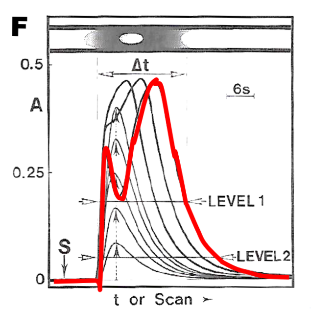
- Response splits into a double peak and will be nonlinear at higher concentration of calibration range
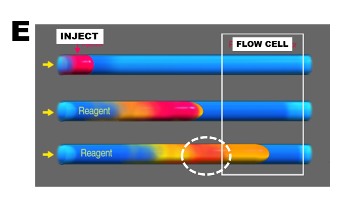
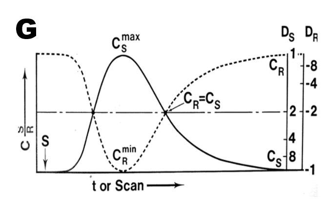
In the single line manifold (E) the injected sample (red) blends with reagent, by dispersion into carrier stream. The reaction product (yellow), to be measured forms gradually on the way to flow cell. A double peak will be recorded when conversion of sample material into (yellow) product during passage through flow cell will not be complete. Therefore increasing injected sample volume (F) will gradually lead to shortening of linear range and ultimately to formation of a double peak.
