3.2.6. Instruments and Components
pF-LOV Instrument
All experiments discussed in this tutorial were performed by using miniSIA instrument available from Global FIA. Alternatively, a pFI-LOV instrument can be assembled from components as below mentioned.
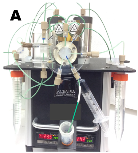
The miniSIA instrument (A)
is designed with the lab-on-valve (LOV) manifold as its centerpiece. The configuration of the flow path on the LOV manifold is different from the traditional FI design, since the holding coils are situated upstream of the injection point. Unlike conventional SIA manifolds, this LOV manifold contains a confluence point where flow from the two holding coils meet. The instrument is equipped with two milliGAT pumps, two temperature-controlled holding coils, lab-on-valve module called Chem-on-Valve (COV) by Global FIA, bolt-on flow cell, fiber optic cables for spectrophotometric detection, a tungsten-xenon and white LED light source and the Ocean Insight (formerly Ocean Optics) Flame Spectrophotometer.
 The miniSIA instrument is controlled by FloZF software for flow programming and data acquisition and manipulation. It uses DI water as carrier, while reagent volumes are in the range of 10 to 200 microliters per assay.
Key components
milliGAT pump (B) has four spring-loaded Teflon-tipped pistons mounted in a rotor. As the rotor turns a cam causes fluid to be dispensed from one piston as its opposite piston aspirates fluid into the piston and the other two pistons move between the aspirate and dispense positions.
The pFI-LOV instrument uses two high-flow (M50) low-pressure pumps. Since in all pFI protocols DI water is used as carrier, the pumps were always, also when idle, filled with water and therefore never come in contact with reagents or samples. Used in this way, pump heads lasted about two years of daily use before it had to be serviced by manufacturer.
B
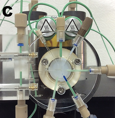
The lab-on-valve module (C) includes the confluence point at the center of the valve, flow-through sample injection port, reagent ports and an externally-mounted bolt-on flow cell. The flow cell, shown here with 1 cm long optical path, can be extended up to 50 cm or replaced by flow cell designed for fluorescence or for chemiluminescence.
Lab-on-valve manifold, machined from a transparent acrylic polymer is mounted atop Valco multi-position valve. In all experiments and pFI publications discussed in this Chapter, the six-position valve, as shown here, was used. It is essential to block and flood (with DI) the ports which are not in use to prevent intrusion of air into flow channels. An eight-port model is also available. LOV manifolds are compatible with external modules: flow cells, external columns, SPE cartridges and internal micro-columns. In laboratory conditions LOV manifold lasted about 200 000 cycles, without need for servicing. A wide variety of reagents were used, including strong acids and bases (up to 1 M) without harm to LOV system, provided that manifold lines were thoroughly flushed and filled with DI water when not in use. Note that organic solvents were not used and for column elution in BI mode methanol content was no higher than 60%.

The mini SIA configured for VIS spectrophotometry comprises:
- Ocean Insight spectrophotometer (former Ocean Optics) USB 4000
- Tungsten-Xenon light source (550-900 nm)
- White LED (450-675 nm)
- Linear Long Light Path flowcells
- Assorted spare tubing and connectors
Adjustments and alternatives
The miniSIA instrument, used for work discussed in this Chapter was supplemented with the following components.
- External tungsten light source Ocean Insight Tungsten Halogen light source (HL-2000), Ocean Insight, Largo, Florida, USA) with higher light output was used, because light intensity of built in tungsten lamp was not sufficient for LLLP flow cell and for phosphate spectrophotometry performed at 880 nm.
- The pressure relief valves mounted between milliGAT pumps and holding coils were removed, dismantled and their part the 40psi back-pressure regulator was mounted at the end of waste line downstream of flow cell, to prevent formation of micro bubbles in flow channel. (The purpose of the pressure relief valve is to avoid over pressurizing the pump in the event of a dead-head or blockage while dispensing).
- Fittings and ferrules were replaced by items described in Ch. 2.1.7.1. (see C)
Alternatives
As advantages of pFI will become gradually recognized, proliferation of the method, inevitably, will not be restrained by availability instrument from a sole source and “self-made” constructs will be assembled. This happened when FIA was invented 40 years ago and will, hopefully, happen again. Modification of existing SI-LOV instrument by amending it with second syringe pump and holding coil is an easy solution accessible to many, who published work using Sequential Injection. It is important, however, to use only high precision syringe pumps (such as Cavro (Tecan) 2 mL) controlled by suitable software, if milliGAT pump is unavailable.
Starting with individual components, LOV module mounted on Valco six port valve has been used (117 references in Hansen’s Database). Note that precise machining of LOV is far preferrable to 3D printing, because it produces smooth surfaces and can use chemical resistant transparent polymers. LLLP flow cell is easily home made (see Guest Contributions). As mentioned above, high precision glass barreled, Teflon piston stepper motor driven pumps are likely to provide adequate fluidic control. It is recommended to test performance of an instrument by dye experiments as discussed in section 3.2.2.