From continuous to programmable flow
In Flow Analysis sample is transported through series of stages, designed to facilitate chemical reactions and to perform associated operations, into a flow through detector, where analytes are monitored and quantified. The finding of this automated process is a result that quantifies content of an identified analyte. This description applies to flow injection analysis as well as to chromatography.
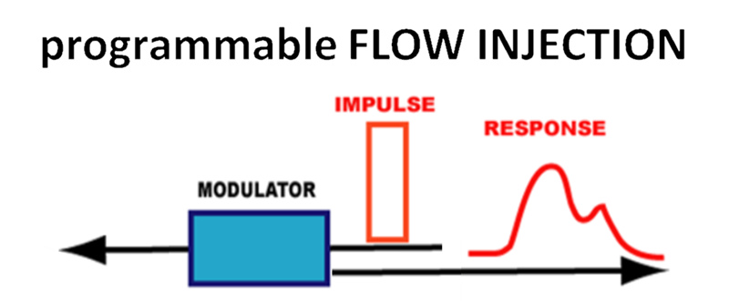
 Majority of flow based analytical methods use continuous and constant forward flow to transport sample from injector to detector and can be therefore characterized as impulse-response techniques.
/4-1-Concept-and-principles/4_1-1-(2).png.aspx)
cFA is an impulse-response technique based on injection of sample as a rectangular input, that results in a response that yields quantitative information on content of target analytes. There are two types of modulators: reactor, column, and their combinations.
/4-1-Concept-and-principles/4_1-2-(2).png.aspx?width=800&height=152)
There are two types of moderators: reactors used to mix sample with reagents and to facilitate chemical reactions, and packed columns used to separate sample components by creating differences in their migration velocities on the way to detector. Flow Injection techniques use reactors while chromatography uses a variety of columns packed with stationary phase.
Use of constant forward flow limits the way in which chemical reactions can be facilitated in a flow through reactor and monitored in flow through detector. Principles and applications of flow programming in Flow Injection are discussed in Chapter 3 and use of flow programming for Chromatography in Chapter 4.
Arresting reaction mixture in reactor by stopping the flow with aim to increase incubation time of sample on the way to detector is only one of many ways flow programming can be used to optimize assay protocol. Comprehensive flow programming includes flow reversals, flow accelerations, and stream merging at a range of flow velocities. This is accomplished in a flow system where modulator is placed upstream from injector.
 pFI is an impulse-response technique based on injection of sample as a rectangular input, that travels upstream from injection point into a reactor where target analyte is processed. Following flow reversal brings reaction mixture into flow cell, yielding a response that provides quantitative information on content of target analytes. The flow system can be configured in two ways: as sequential injection (SI), driven by a single pump or programmable flow injection (pFi), driven by two pumps.

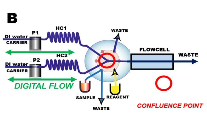
The centerpiece of programmable FI system is a multiposition valve that facilitates aspiration of precise volumes of sample and reagents into holding coil (HC) that serves as reactor. Deionized water is used as carrier, a feature that reduces reagent consumption and facilitates cleanup of flow channel. There are two configurations of flow manifold sequential injection and programmable FI.
Programable FI automates reagent-based assays more efficiently then cF but also enabled novel techniques which cannot be performed in any other way, such as fully automated:
Flow Injection Analysis
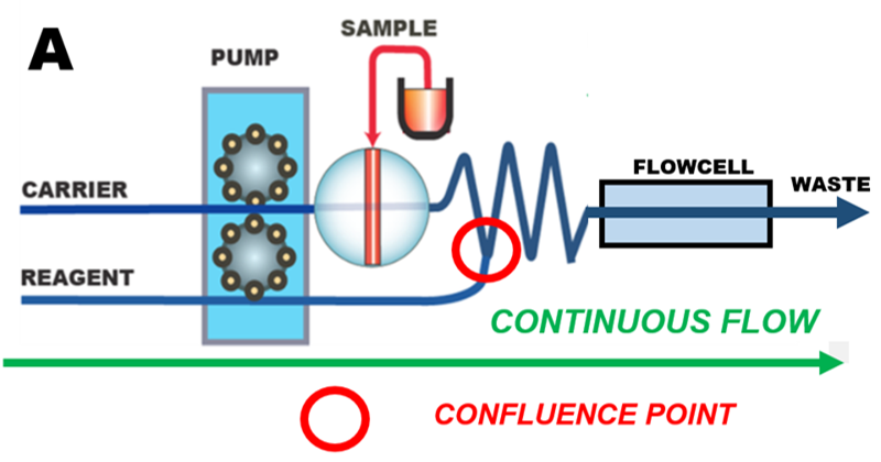
In Flow Injection Analysis a non-segmented carrier solution transports a defined sample volume through confluence point(s) where reagents are added to form products that are monitored by flow through detector. Associated operations such as separation by sorbent, or by gas diffusion, can also be included in the flow path.
In continuous Flow Injection (cFI) system (A), a carrier stream, usually propelled by peristaltic pump, moves in forward direction at constant flow rate. A two-position valve is used to inject a defined sample volume into carrier that merges with reagent stream at a confluence point, and moves into a coiled conduit, where chemical reactions take place on the way into flow through detector.
The continuous flow format is widely used because it is easy to construct and operate, it offers high sampling frequency and a because it has been established for over 40 years. While cFI is a very efficient tool for performing serial assays, its drawback is consumption of large volumes of reagents and generation of waste, because solutions are being continuously pumped at a rate of several milliliters per minute. Also, to accommodate various assay protocols flow path of cFI instrument must be reconfigured (by changing number of confluence points and reactor coils). In contrast, in pFI mode diverse assays are accommodated by changing software protocol.

Core of programmable Flow Injection system (B) is the confluence point at the center of a multiposition valve. Sample and reagent solutions move back and forth through this point into holding coils and ultimately into flow through detector by means of pumps (P1 and P2) by deionized water used as a carrier. Digitalized microfluidic manipulations aspirate precise volumes of sample and reagents via ports of multiposition valve, mix and transport them through series of preprogrammed flow reversals into holding coils (H1 and H2) and ultimately into flow cell.
 Programmable FI and its predecessor Sequential Injection operate in microliter scale in discontinuous flow fashion and therefore use approximately 20x less of reagent than cFI. Almost all pFI assay protocols use deionized (DI) water as carrier stream, which facilitates washout and maintenance of the flow system, of pumps and of detectors. Computer controlled microfluidic manipulations: accelerated, reversed, and stop flow offer unpreceded versatility and longtime reproducibility that cFI cannot match. Single Standard Solution Calibration and Bead Injection. are techniques that can only be performed by means of flow programming.
Majority of reagent-based assays use spectrophotometry to quantify an analyte, because chromogenic reagents produce species with well-defined spectra. The absorbance, proportional to concentration of analyte can be measured while sample zone moves through the flow cell, or when it is trapped within the flow call by stopping the flow.
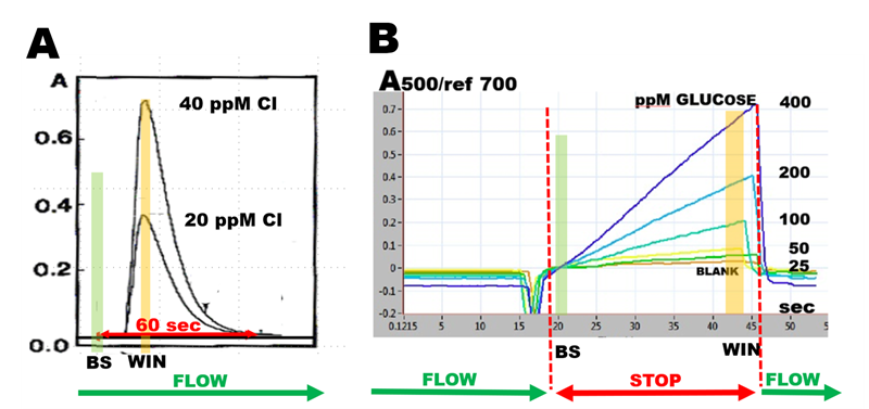
Flow through monitoring yields a peak (A) the height of which is proportional to concentration of analyte. Computerized data collection produces absorbance values as a difference between baseline (BS) and maximum value captured within data collection window (WIN). Stopped flow monitoring (B) yields a reaction rate response that can be quantified in the same way as flow through response. It is also used as a tool for optimization of assay protocol because it provides insight into progress of chemical reactions.

It follows from the foregoing that “The flow injection response curve is result of two processes, both kinetic in nature: the physical process of dispersion of sample zone within carrier stream, and chemical process of formation chemical species.”
Therefore, in continuous flow system room for assay optimization is limited because increase of incubation time, that promotes yield of chemical reaction, is tied to increase in dispersion of sample zone. When flow is discontinued by flow programming, increase of incubation time is obtained by stopping the flow, while dispersion of sample zone, promoted by forward flow is stopped.
J.Ruzicka and E. H. Hansen. “Flow injection analysis. Part X. Theory.” Anal. Chim. Acta, 99, (1978) 37.